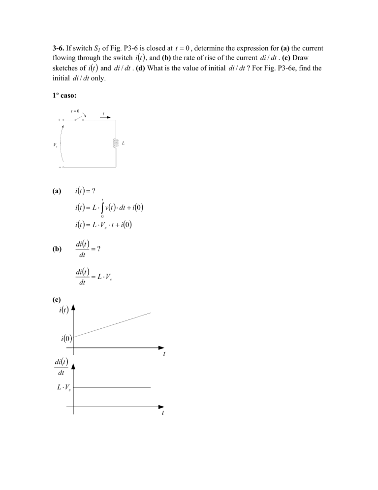
3-6. If switch S1 of Fig. P3-6 is closed at t = 0 , determine the expression for (a) the current
flowing through the switch i (t ) , and (b) the rate of rise of the current di / dt . (c) Draw
sketches of i (t ) and di / dt . (d) What is the value of initial di / dt ? For Fig. P3-6e, find the
initial di / dt only.
1º caso:
t =0
i
+
L
Vs
−
i (t ) = ?
(a)
t
i (t ) = L ⋅ ∫ v(t ) ⋅ dt + i (0 )
0
i (t ) = L ⋅ Vs ⋅ t + i(0 )
(b)
di(t )
=?
dt
di (t )
= L ⋅ Vs
dt
(c)
i (t )
i (0 )
di(t )
dt
t
L ⋅ Vs
t
di (t )
=?
dt t =0
(d)
di (t )
= L ⋅ Vs
dt t =0
2º caso:
t=0
+
R
Vs
C
Vo
−
i (t ) = ?
A forma de onda da corrente i (t ) é uma função exponencial que pode ser escrita da
seguinte forma:
(a)
i (t ) = i (∞ ) + [i (0 ) − i (∞ )] ⋅ e
−
t
τ
Na qual: i (0 ) é o valor inicial da corrente, i (∞ ) é o valor final e τ é a constante de
tempo.
Se o capacitor está inicialmente descarregado temos:
Vs − vc (0 )
R
Depois que o capacitor carregar-se, não haverá corrente no circuito. Assim:
i (0 ) =
i (∞ ) = 0
A constante de tempo é:
τ = RC
Então:
V − vc (0) − RC
i(t ) = s
⋅e
R
t
(b)
di(t )
=?
dt
V − v (0 ) −
di (t )
= − s 2 c ⋅ e RC
dt
R ⋅C
t
(c)
i(t )
Vs − vc (0 )
R
di(t )
dt
τ
t
τ
t
−
Vs − vc (0 )
R2 ⋅ C
(d)
di (t )
=?
dt t =0
V − v (0 )
di(t )
=− s 2 c
dt t =0
R ⋅C
3º caso:
t=0
+
R
i
L
Vs
−
i (t ) = ?
A forma de onda da corrente, i (t ) , é uma função exponencial pode ser escrita da
seguinte forma:
(a)
i (t ) = i (∞ ) + [i (0 ) − i (∞ )] ⋅ e
−
t
τ
Pelo circuito verifica-se que a condição inicial do indutor necessariamente é nula,
então:
i (0 ) = 0
Depois que a chave é fechada, a tensão no resistor aumentará até se igualar a tensão
da fonte. Assim, temos:
i(∞ ) =
Vs
R
A constante de tempo é:
τ=
L
R
Então:
V
i(t ) = s
R
(b)
di(t )
=?
dt
R⋅t
−
1 − e L
di (t ) Vs − L
= e
dt
L
R ⋅t
(c)
i (t )
Vs
R
τ
di(t )
dt
t
Vs
L
t
τ
(d)
di (t )
=?
dt t =0
V
di (t )
= s
dt t =0 L
4º caso:
t=0
i
+
L
Vs
C
Vo
−
A equação diferencial que rege o circuito é:
Vs − L
di 1
− ⋅ i (t ) ⋅ dt − vc (0 ) = 0
dt C ∫
Sua transformada de Laplace é:
Vs
v (0 )
1
− L(s ⋅ I (s ) − i (0 )) −
⋅ I (s ) − c
=0
s
s ⋅C
s
Pelo circuito nota-se que a corrente inicial no indutor necessariamente é zero, assim:
L ⋅ s ⋅ I (s ) +
I (s ) =
V − vc (0 )
1
⋅ I (s )+ = s
s ⋅C
s
(Vs − vc (0))
s
Na qual ω = 1
i (t ) =
⋅
C
s ⋅C
ω
⋅ (Vs − vc (0 )) ⋅ 2
=
L
s ⋅ LC + 1
s +ω2
(
2
)
(
)
LC
C
⋅ (Vs − v c (0 )) ⋅ sen (ω ⋅ t )
L
O diodo impedirá que a corrente assuma valores negativos e esta expressão só é
válida para ω ⋅ t < π .
i (t ) 1
= ⋅ (Vs − vc (0)) ⋅ cos(ω ⋅ t )
dt L
(c)
i (t )
L
⋅ (Vs − vC (0 ))
C
π ⋅ LC
di (t )
dt
Vs − vC (0 )
L
π ⋅ LC
t
V − vC (0 )
− s
L
(d)
t
di (t )
=?
dt t =0
i (t ) 1
= ⋅ (Vs − vc (0 ))
dt L
5º Caso
t =0
L1 = 20 µH
+
R = 0.5Ω
Vs
Cf
L1 = 20 µH
−
di (t )
=?
dt t =0
Para o intervalo de tempo infinitesimalmente pequeno após o fechamento da chave, o
seguinte circuito é formado:
L1 = 20µH
+
Vs
−
Pelo qual podemos verificar que:
V − vC (0 )
di (t )
= s
dt t =0
L
vC (0 )
iL (0 )

